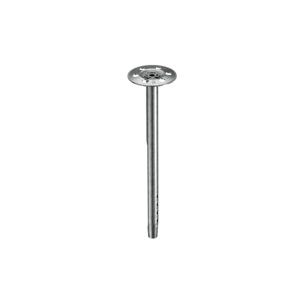

![[ISAD-2] Insulation retainer disc 80mm A2 stainless ISA-S D](/web/image/product.template/6430/image_1920/%5BISAD-2%5D%20Insulation%20retainer%20disc%2080mm%20A2%20stainless%20ISA-S%20D?unique=9a7bbe5)
Insulating anchor for cold-, heat- and fire-protection
The A2 or Zinc-Plated fire rated insulation support anchor. Simply hammer the anchor into the prepositioned insulation, and the anchor will expand into the substrate, securing the load. The hammer
installation allows fast setting and reducing the amount of work.
Features
- Approved for multiple fastenings of insulation panels
- High load-bearing capacity in cracked and non-cracked concrete
- Small drill holes
- Can be coated to any colour within around 5 – 10 working days
- Quick and safe installation
Applications
- Approved for C20/25 – C50/60 concrete
- Approval in both cracked and non-cracked concrete
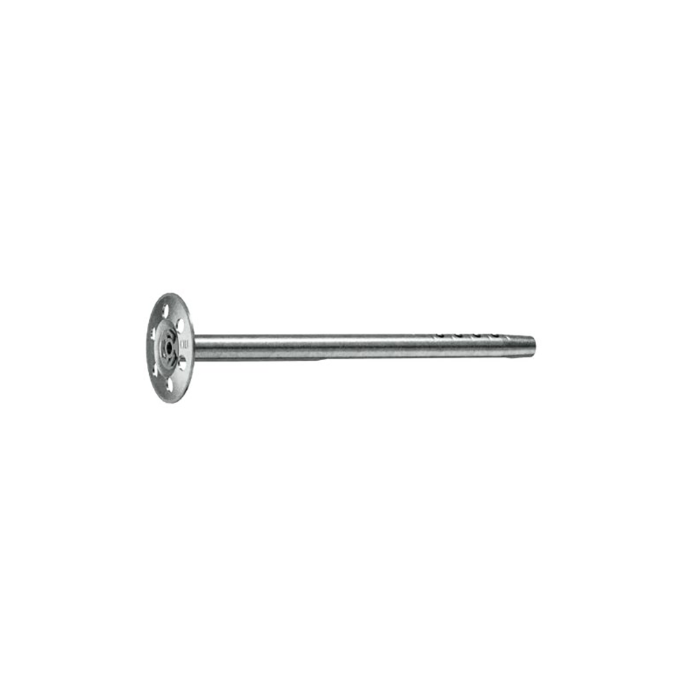
The fire rated insulation support anchor available in either A2 Stainless and Zinc-Plated Steel. Simply hammer the anchor into the pre-positioned insulation, and the anchor will expand into the substrate, securing the load. The hammer installation allows fast setting and reducing the amount of work.
- Approved for C20/25 – C50/60 concrete
- Approval in both cracked and non-cracked concrete
- Approved for multiple fastenings of insulation panels
- High load-bearing capacity in cracked and non-cracked concrete
- Small drill holes
- Quick and safe installation
Technical Characteristics Without Fire Exposure
| ISA-S / ISA-Z Insulation Anchor | |||
Drill Bit Diameter |
d0 |
[mm] |
8 |
|
Depth of Drill Hole |
h1 ≥ |
[mm] |
45 |
|
Effective Anchorage Depth |
hef ≥ |
[mm] |
40 |
|
Minimum Thickness of Member |
hmin |
[mm] |
80 |
|
Edge Distance |
c |
[mm] |
60 |
|
Spacing |
s |
[mm] |
120 |
|
Permissible load in cracked and non-cracked concrete C20/25 – C50/60¹ʾ²ʾ |
Nzul |
[kN] |
0.074 |
The partial safety factor for material resistance from the approval yM = 1.5 as well a partial safety factor for load actions yF = 1.4 were considered for determining the load
Technical Characteristics Under Fire Exposure
| ISA-S / ISA-Z Insulation Anchor | |||
|
Fire Resistance Class |
|||
|
R 30 |
Permissible Load Ffi,per,30 1) |
[kN] |
0.09 |
|
R 60 |
Permissible Load Ffi,per,60 1) |
[kN] |
0.09 |
|
R 90 |
Permissible Load Ffi,per,90 1) |
[kN] |
0.09 |
|
R 120 |
Permissible Load Ffi,per,120 1) |
[kN] |
0.09 |
|
R 180 |
Permissible Load Ffi,per,180 1) |
[kN] |
0.06 |
|
R 30 – R 120 |
Spacing sfi Edge Distance cfi |
[mm] |
120 |
The partial safety factor for material resistance from the approval yM = 1.0 as well a partial safety factor for load actions yF = 1.0 were considered for determining the load.
Installation Instructions

- Set drill hole
- Clean out drill hole from the base
- Knock insulation fastener through the insulation panel with a hammer
- Anchor disc must fully contact the insulation panel
Minimum 4 anchors per square meter for insulation panel. The dimension between axes and edge distance is valid without fire exposure. Assumed that an application is forced with fire exposure.